
Industrial Connector Installation: How to Prevent Connection Failures
Learn how to prevent industrial connector failures through correct mating, cable termination, sealing, strain relief, and installation checks.
Follow us now:
- Industrial Connector Installation: How to Prevent Connection Failures
- 1. Why Installation Quality Matters for Industrial Connector Reliability
- Correct Connector Selection Does Not Guarantee a Reliable Connection
- How Installation Errors Become Operational Failures
- 2. Common Industrial Connector Installation Mistakes
- Incomplete Mating and Incorrect Locking
- Incorrect Cable Preparation and Termination
- Damaged Seals and Incorrect Cable Entry
- Poor Cable Routing and Insufficient Strain Relief
- Incorrect Pin Assignment or Connector Pairing
- 3. How to Prevent Connection Failures in Real Industrial Applications
- Sensor and Automation Equipment
- Outdoor and Moisture-Exposed Equipment
- Robotics and Moving Machinery
- Control Cabinets and Modular Machines
- 4. Installation Checks Before Commissioning
- Check Connector Compatibility and Pin Configuration
- Verify Mating, Locking, Sealing, and Cable Fixation
- Perform Appropriate Electrical and Functional Tests
- 5. How Connector Design Affects Installation Reliability
- Locking Mechanisms and Mating Procedures
- Environmental Protection and Sealing
- Cable Assemblies and Standardized Installation
- 6. Choosing the Right WEIPU Connector and Cable Assembly
- Circular Connectors for Compatible Equipment Interfaces
- Heavy-Duty Connectors for Multi-Circuit Connections
- Preassembled Cable Solutions for Repeatable Installation
- 7. Industrial Connector Installation Checklist
- Conclusion
- FAQ
Industrial Connector Installation: How to Prevent Connection Failures
Industrial connectors are designed to provide reliable electrical connections in demanding environments. However, even a correctly selected connector can experience connection problems if it is installed, terminated, or maintained incorrectly.
Incomplete mating, improper cable termination, damaged seals, poor cable routing, and incorrect pin assignments can all affect connection reliability. Depending on the application, these issues may lead to intermittent signals, unexpected equipment downtime, moisture ingress, or additional maintenance work.
Reliable industrial connectivity depends on more than connector design. It also depends on installation quality, cable preparation, mechanical support, and verification before commissioning.
This article explains common industrial connector installation mistakes, how they can affect equipment performance, and what engineers and technicians can do to prevent connection failures in real industrial applications.
1. Why Installation Quality Matters for Industrial Connector Reliability
Industrial connectors form the physical interface between power supplies, sensors, actuators, controllers, communication devices, and other equipment. Their performance depends on the compatibility of the components and the quality of the complete connection.
Correct Connector Selection Does Not Guarantee a Reliable Connection
Selecting a connector with the appropriate electrical ratings and environmental protection is an important first step. However, the intended performance also depends on whether the connector is correctly paired, assembled, installed, and used within its specified operating conditions.
For example, a connector designed for an application involving moisture may not provide the expected protection if its sealing components are damaged or its mating interface is incorrectly assembled. Similarly, a connector intended for a vibrating machine may experience connection problems if the cable is poorly supported or the coupling mechanism is not properly engaged.
Installation quality must therefore be considered alongside connector selection.
How Installation Errors Become Operational Failures
Different installation errors can produce different symptoms:
-
Intermittent electrical connections: Incomplete mating, damaged contacts, or inadequate termination may interrupt the electrical path.
-
Unstable signals or communication: Incorrect wiring, unsuitable termination, or connection instability may affect signal transmission.
-
Moisture or dust ingress: Damaged seals, incompatible accessories, or incorrect assembly may compromise environmental protection.
-
Mechanical damage: Poor cable routing, excessive pulling force, or repeated bending may place stress on the connector and cable.
-
Longer troubleshooting time: Missing identification, incorrect pin assignments, and inconsistent wiring can make faults harder to locate.
Not every symptom has a single cause. A structured inspection process helps distinguish installation problems from component defects, cable faults, and wider system issues.
2. Common Industrial Connector Installation Mistakes
Understanding common installation errors helps engineers develop practical procedures for assembly, commissioning, and maintenance.
Incomplete Mating and Incorrect Locking
A connector may appear connected without being fully engaged. Depending on its design, incomplete mating can prevent the contacts or sealing components from reaching their intended operating position.
Incorrectly engaged locking mechanisms may also allow a connection to loosen under vibration or cable movement.
To reduce these risks, technicians should follow the installation instructions for the specific connector model. They should confirm that the connector has reached its intended mating position and that the specified locking mechanism is properly engaged.
Do not assume that every connector uses the same mating procedure. Threaded, push-pull, and bayonet connectors have different operating principles and must be handled according to their individual designs.
Incorrect Cable Preparation and Termination
Cable termination is another important factor in connection reliability. An incorrectly prepared conductor or poorly executed termination may lead to unstable electrical contact, increased resistance, localized heating, or a conductor that becomes loose under mechanical stress.
Common mistakes include:
- Using an unsuitable stripping or termination tool
- Removing too much or too little insulation
- Selecting a termination method that does not match the connector
- Failing to secure the conductor correctly
- Applying cable tension directly to the termination
- Skipping the required inspection after assembly
The appropriate prevention method depends on the contact design. Crimping, soldering, and screw termination require different tools, procedures, and quality checks.
For crimped contacts, for example, the terminal, conductor size, and crimping tool must be compatible. For soldered connections, the specified soldering procedure should be followed without damaging insulation or adjacent components.
Where cable assemblies are produced repeatedly, documented termination procedures and consistent inspection criteria can help reduce variation between assemblies.
Damaged Seals and Incorrect Cable Entry
In applications exposed to dust, moisture, cleaning processes, or outdoor conditions, the sealing arrangement must be installed correctly.
Potential problems include damaged or missing seals, incompatible cable diameters, incorrect accessories, contaminated mating surfaces, and improper assembly of the connector's cable entry.
These issues may compromise the intended environmental protection even when the connector itself has a published IP rating.
Before installation, inspect the relevant sealing components and verify that the connector, cable, and accessories match the specified configuration. Follow the manufacturer's instructions for assembly, tightening, and maintenance.
Engineers should also distinguish between the connector's specified protection rating and the protection achieved by the complete installed connection.
Poor Cable Routing and Insufficient Strain Relief
A connector should not be expected to support the mechanical load of an inadequately routed cable.
Excessive pulling force, sharp bends, repeated movement, or unsupported cable weight may stress the connector interface and termination. Over time, these conditions can contribute to mechanical damage or intermittent electrical problems.
To reduce unnecessary stress:
-
Route cables away from sharp edges and pinch points.
-
Follow the cable manufacturer's specified minimum bend radius.
-
Use suitable clamps, cable supports, and strain-relief arrangements.
-
Keep cable loads from being transferred directly to electrical contacts.
-
Provide sufficient clearance around connectors for installation and maintenance.
-
For moving equipment, verify that the cable is suitable for the required movement and service life.
These precautions are particularly important in robotics, automated machinery, and equipment with moving modules.
Incorrect Pin Assignment or Connector Pairing
A connector may fit physically while its contact configuration or wiring assignment is incompatible with the intended application.
Incorrect pin assignments can prevent equipment from operating properly and may create electrical risks if incompatible circuits are connected.
Before assembly, technicians should check the connector model, contact configuration, pin assignment, cable drawing, and mating counterpart. Keying and coding features should be used as intended, but they should not replace documentation checks.
For equipment manufactured in batches, controlled drawings and clearly identified cable assemblies help maintain consistent connections across machines.
3. How to Prevent Connection Failures in Real Industrial Applications
Installation procedures should reflect the actual environment and mechanical requirements of the equipment. The following scenarios illustrate how connector installation quality affects different industrial applications.
Sensor and Automation Equipment
Industrial sensors connect measurement and detection functions to control systems. Depending on the application, these connections may carry power, switching signals, analog signals, or communication data.
Common installation concerns include incomplete mating, incorrect pin assignments, poor cable fixation, and limited access to the connector interface.
To reduce these risks, engineers should verify the sensor's electrical interface, connector configuration, cable assignment, and installation clearance before commissioning.
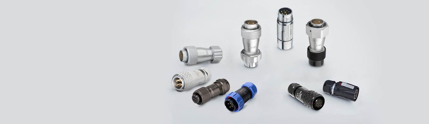
Suitable WEIPU circular connector options, including compatible SA, SF, WF, or WK configurations, can be evaluated according to the requirements of the particular sensor and equipment.
The selected model must match the required contact arrangement, electrical ratings, mounting method, and environmental conditions. A connector series should not be assumed suitable for every sensor application without checking its specifications.
Outdoor and Moisture-Exposed Equipment
Outdoor machinery, energy equipment, and industrial installations exposed to moisture require careful attention to connector sealing and cable entry.
For example, a connection may have an appropriate specified IP rating but still be vulnerable if the sealing components are damaged, the mating parts are incompatible, or the cable entry is assembled incorrectly.
Before commissioning, check the sealing components, connector compatibility, cable entry, and assembly condition. Confirm that the installed connection meets the environmental requirements of the application.
WEIPU connector families such as SP series, SA series, and SF series may be considered where the specific model and configuration meet the required protection and electrical specifications.
The actual installation must follow the product documentation. An IP rating should not be interpreted as permission to expose a connector to every type of moisture, pressure, chemical, or cleaning condition.
Robotics and Moving Machinery
Robots, automated guided vehicles, and other moving equipment introduce additional mechanical challenges. Cables may bend, twist, or move repeatedly, while vibration and acceleration can place stress on connector interfaces.
A connector that performs well in a stationary installation may not be suitable for a dynamic application if the cable, strain relief, routing, or connector configuration is not designed for the required movement.
Engineers should evaluate the complete connection assembly, including the connector, cable, coupling mechanism, cable support, and movement profile.
Where appropriate, compatible WEIPU SP, WY, or M23 configurations can be considered as part of the connection design. However, suitability for repeated movement must be verified from the technical documentation for the specific connector and cable assembly.
Correct installation can reduce avoidable mechanical stress, but it cannot compensate for a cable or connector that is unsuitable for the application's motion requirements.
Control Cabinets and Modular Machines
Control cabinets and modular machines often contain many electrical interfaces. Incorrect pin assignments, inconsistent cable lengths, poor identification, and inaccessible connectors can complicate commissioning and maintenance.
A practical approach is to define connector interfaces and cable assemblies before equipment assembly begins. Each connection should have a documented function, pin assignment, cable specification, and identification method.
Preassembled cable solutions may help standardize repeated connections and reduce the amount of field termination required. Their effectiveness depends on accurate engineering documentation, correct assembly, and suitable quality checks.
For modular equipment, connector locations should also allow technicians to access the interface safely when modules need to be inspected or replaced.
4. Installation Checks Before Commissioning
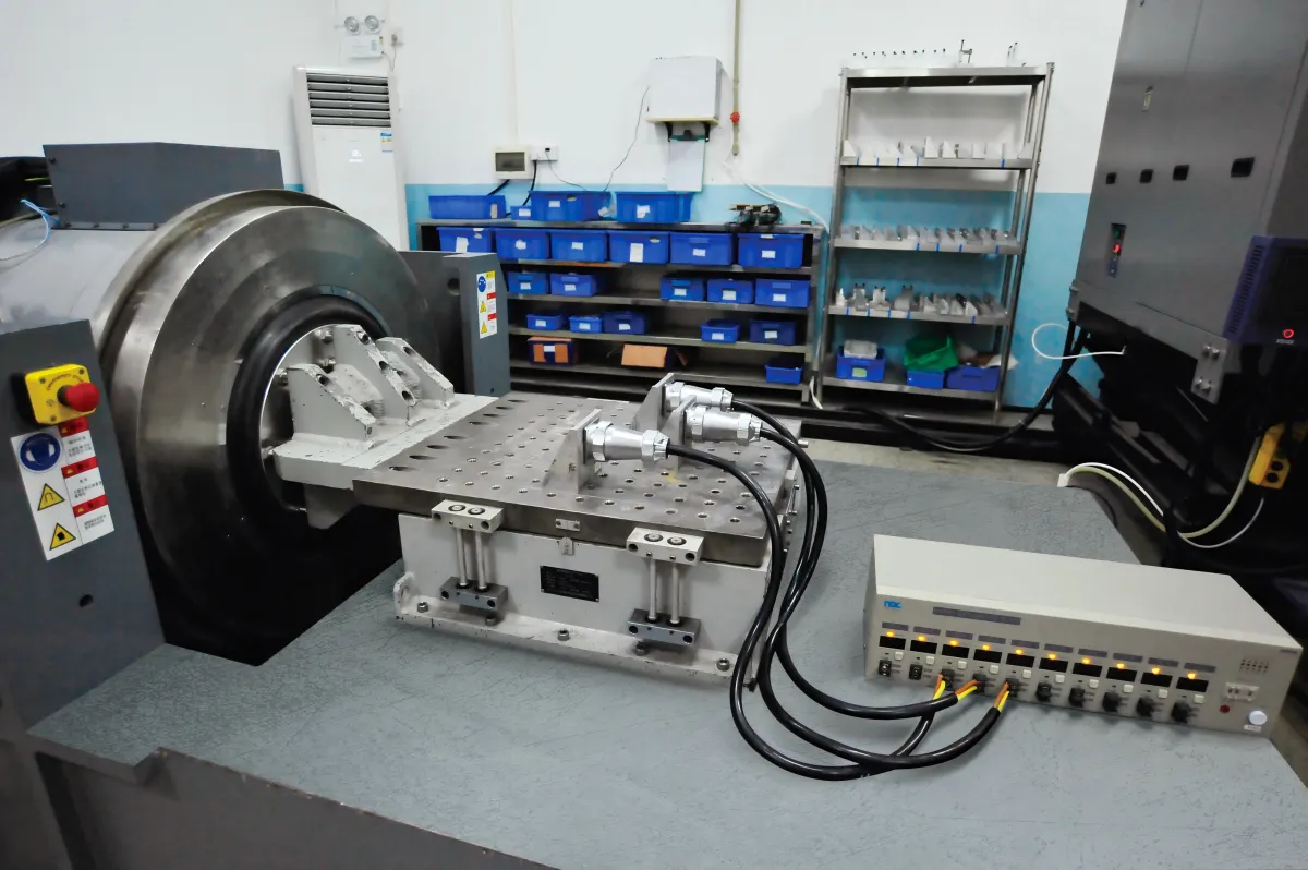
Installation should not be considered complete simply because all connectors appear to be connected. A structured verification process helps identify errors before equipment enters operation.
Check Connector Compatibility and Pin Configuration
Before energizing the system, confirm that the connector models, mating counterparts, contact configurations, and wiring assignments match the approved drawings.
Check that:
- The connector and mating counterpart are compatible.
- Contact arrangements match the intended electrical function.
- Cable assignments and pin numbers are correct.
- Contacts and insulation show no visible assembly damage.
- Unused contacts are handled according to the product and system requirements.
Verify Mating, Locking, Sealing, and Cable Fixation
Inspect each connection according to its specific installation requirements.
Confirm that the connector is fully mated, its locking mechanism is correctly engaged, and its sealing components are properly installed where applicable. Check that cables are supported and do not impose excessive force on the connector.
Where the connector requires a specified tightening method or torque, follow the product documentation rather than estimating the required force.
A visual inspection can identify many assembly issues, but it cannot confirm every electrical or environmental performance characteristic.
Perform Appropriate Electrical and Functional Tests
The test procedure should reflect the connector, equipment, and application requirements.
Depending on the system, verification may include:
- Continuity testing to confirm the intended electrical path
- Pin-to-pin checks against the wiring diagram
- Insulation testing where required and compatible with connected equipment
- Functional checks of sensors, actuators, and control signals
- Communication testing for connected devices
- Appropriate inspection or validation of the installed sealing arrangement
Electrical tests must be performed using approved procedures and suitable equipment. Insulation testing, in particular, should not be applied indiscriminately to connected electronics or communication interfaces.
The objective is to verify the complete connection against its intended function before the equipment enters service.
5. How Connector Design Affects Installation Reliability
Installation quality is influenced by the connector's design, the selected cable, the assembly method, and the accessibility of the connection point.
Locking Mechanisms and Mating Procedures
Different coupling mechanisms have different installation requirements. Threaded connectors, push-pull connectors, and bayonet connectors should each be operated according to the instructions for the selected model.
Engineers should consider the installation space, expected mating frequency, vibration exposure, and the ease with which technicians can verify that a connection is secure.
A suitable locking mechanism can help maintain the intended connection, but correct mating and cable support remain essential.
Environmental Protection and Sealing
For applications exposed to dust or moisture, the connector's specified environmental protection must be considered alongside the installed configuration.
Correct mating, compatible accessories, intact seals, and proper cable entry all contribute to achieving the intended protection. Installation and maintenance procedures should also account for seal inspection and replacement where specified.
Cable Assemblies and Standardized Installation
Cable assemblies can help standardize connection arrangements across repeated equipment builds.
Depending on the application, a preassembled cable may arrive with specified connector configurations, cable length, conductor arrangement, and termination. This can reduce the amount of field wiring and help make assembly more repeatable.
However, cable assemblies must still be matched to the equipment design. Connector compatibility, cable characteristics, pin assignments, and environmental requirements should be checked before installation.
6. Choosing the Right WEIPU Connector and Cable Assembly
The connector should be selected according to the application requirements, and its installation procedure should be defined as part of the complete connection solution.
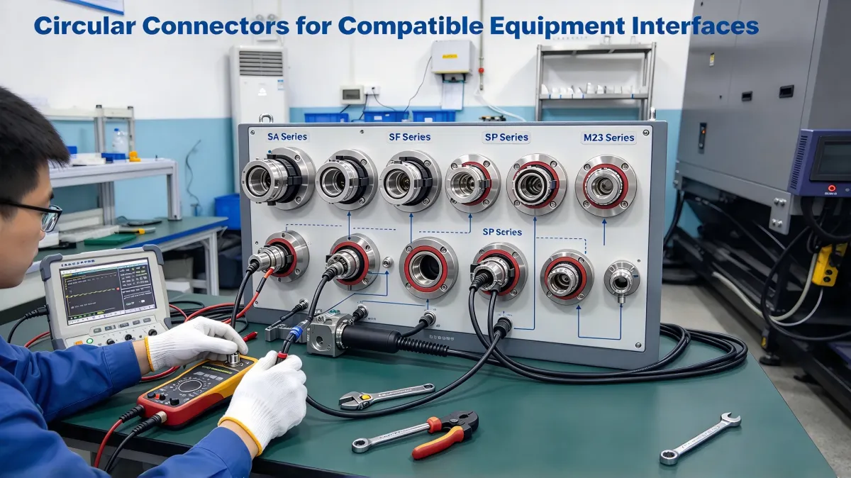
Circular Connectors for Compatible Equipment Interfaces
WEIPU circular connector families may be suitable for selected sensor, automation, and industrial equipment interfaces.
Options such as the SA Series, SF Series, SP Series, and M23 Series offer different designs and configurations.
Before choosing a model, engineers should confirm the electrical ratings, contact arrangement, coupling method, mounting requirements, and environmental specifications.
Installation procedures must then be adapted to the actual connector design. Instructions for one series should not automatically be applied to another.
Heavy-Duty Connectors for Multi-Circuit Connections
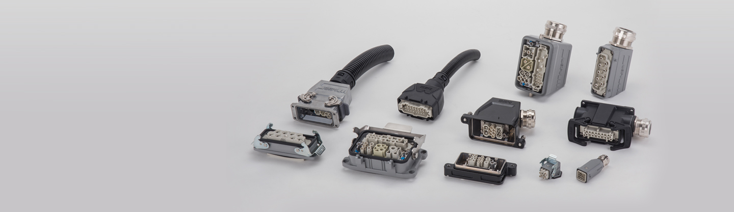
Where a machine interface requires multiple power and control circuits, suitable heavy-duty connector configurations may provide a structured connection between equipment sections, electrical enclosures, and auxiliary assemblies.
The selected housing, insert arrangement, contact configuration, cable entry, and protection requirements must match the application.
For maintenance and commissioning, clear circuit identification and documented wiring assignments are particularly important when multiple circuits share the same connector assembly.
Preassembled Cable Solutions for Repeatable Installation
For OEM equipment manufactured in repeated configurations, a defined cable assembly can help standardize connector combinations, cable lengths, and termination arrangements.
A well-specified assembly should identify the connector models, pin assignments, cable characteristics, length, and any application-specific requirements.
This can simplify installation and inspection, provided the assembly is manufactured to the correct specification and verified before use.
For projects involving customized cable assemblies, engineers should work from approved drawings and confirm compatibility with the equipment before installation.
7. Industrial Connector Installation Checklist
Use the following checklist as a starting point for connector assembly, equipment commissioning, and maintenance. Adapt it to the specific connector, equipment, and applicable safety procedures.
-
Compatibility: Confirm the connector model and mating counterpart.
-
Electrical configuration: Verify contact arrangement, pin assignment, voltage, and current requirements.
-
Cable preparation: Use the specified conductor size, stripping method, and termination process.
-
Contact condition: Inspect contacts, insulation, and termination quality for visible damage or assembly defects.
-
Mating: Confirm that the connector is fully engaged according to its design.
-
Locking: Verify that the coupling mechanism is correctly secured.
-
Sealing: Check seals, cable entries, and accessories where environmental protection is required.
-
Cable management: Check routing, bend radius, support, and strain relief.
-
Identification: Confirm that cables and interfaces are labeled consistently with the approved drawings.
-
Verification: Perform the electrical and functional checks required for the application.
-
Documentation: Record inspection results and any corrective actions according to the site's quality procedures.
This checklist helps structure the installation process, but it does not replace the manufacturer's instructions, equipment-specific procedures, or applicable electrical safety requirements.
Conclusion
Industrial connector reliability depends on more than the connector itself. Incomplete mating, incorrect termination, damaged seals, poor cable routing, and inadequate verification can all compromise a connection, even when the selected connector is appropriate for the application.
By following model-specific installation instructions, using compatible cable and termination components, supporting cables properly, and verifying connections before commissioning, engineers and technicians can reduce avoidable installation-related problems.
For equipment manufacturers, standardized cable assemblies and documented connection interfaces can also improve consistency across repeated builds and simplify maintenance.
WEIPU connector and cable assembly solutions should therefore be evaluated as part of a complete connection system, with product selection, installation procedures, and verification requirements considered together.
Reliable industrial connectivity is not achieved by selecting the right connector alone. It requires the right connector, correctly installed and properly verified.
FAQ
1. What are the most common industrial connector installation mistakes?
Common mistakes include incomplete mating, incorrect locking, poor cable termination, damaged seals, incorrect pin assignments, and inadequate cable support. The resulting problems depend on the connector design and operating conditions.
2. Can incorrect connector installation cause intermittent signals?
Yes. Incomplete mating, damaged contacts, unsuitable termination, or mechanical stress can interrupt an electrical path and may contribute to intermittent signals. However, communication problems can also originate from cables, devices, configuration, or other system components, so diagnosis should consider the complete connection.
3. How can technicians check whether an industrial connector is installed correctly?
Technicians should verify connector compatibility, pin assignments, termination quality, mating and locking status, sealing components where applicable, and cable routing. Appropriate continuity, electrical, communication, and functional tests should be performed according to the equipment and connector requirements.
4. Does an IP67 connector guarantee waterproof performance after installation?
No. An IP rating describes a specified level of protection under defined test conditions. Actual installed performance also depends on correct mating, compatible accessories, intact seals, cable entry, and compliance with the manufacturer's installation instructions.
5. How can cable assemblies improve installation consistency?
Preassembled cable assemblies can standardize connector configurations, cable lengths, and termination arrangements. They may reduce field wiring and variation between equipment builds, provided they are manufactured to an approved specification and checked for compatibility.
Industrial Ethernet Connectivity: How to Choose Reliable Connectors for Automation Networks

How Waterproof Connectors Play An Important Role In Marine Applications

Industrial Connectors for 50 °C+ Ambient: Specifying for Middle East Outdoor Installations

Industrial Connectors for Industrial Ethernet Networks | Reliable Connectivity Guide
Contacts
Sofia
WhatsApp/Phone

Weipu WF Series Industrial Threaded Connectors with IP67 Protection
WEIPU WF Series Industrial Threaded Connectors offer robust IP67 protection, ensuring reliable performance in harsh environments. Designed for secure, waterproof connections, these IP67 connectors are ideal for industrial applications requiring durability and stability. Trust WEIPU for quality and safety.

16A 3PIN Panel mount socket TYP5101-IP44

WEIPU WY-TE Series Waterproof Electrical Plug
With metal clamping-nut IP67, Threaded, Zinc alloy with chrome plating, PPS
WEIPU WY-TE IP67 circular connectors are waterproof electrical plugs with metal clamping-nut, which are durable, safe and easy to assemble with your all devices.With the metal clamping-nut and threaded design, these waterproof electrical plugs ensure high security and super stable connection. It’s an ideal waterproof connector for your applications.

SF610B/P SF610B/S Cable connector IP67
Mate with SF611B, SF612B, SF615B
Get in Touch
Request Related Resources about Industrial Connections & Solutions
If you require technical details, product guides, or specific recommendations from a premier connector manufacturing corporation, please send us your request. We provide expert support for custom electrical connectors, offering OEM/ODM customization and dedicated distributor cooperation assistance.
Weipu Building, No. 111, Baihua Road, Liwan District, Guangzhou, Guangdong China
© 2026 WEIPU. All Rights Reserved.
Whatsapp: +8618102298073
WEIPU
WEIPU
WEIPU
WEIPU